

Questions and answersі
As of February 24, 2022, our company has terminated all ties with the Russian Federation.
Our company produces products certified for compliance with state standards of Ukraine, in particular according to DSTU EN 54-5, DSTU EN 54-7, DSTU EN 54-11, DSTU EN 54-12 and other standards. According to these documents, no fire detectors are characterized by the parameters of their location in the premises. And in accordance with the current standards, the manufacturer is obliged to check the parameters given in the operational documentation during the production process, during acceptance and acceptance or periodic tests.
Parameters for the location of PCs in premises are the area of state building regulations, references to which are given in our documentation.
DBN V 2.5-56-2010 was introduced in Ukraine instead of DBN V. 2.5.-13-98 *. In some operating documents on the PC presented on the website of our company, this replacement has not yet been carried out. But in the design documentation for the main products of our enterprise, notices have already been issued to replace the clauses on the application of IP in the text.
All fire detectors produced by our company and certified for compliance with DSTU EN 54 are necessarily responsible for their application in accordance with the requirements of state building regulations DBN В 2.5-56-2010 without any additional conditions. Our company has no reason to increase or decrease the distance between fire detectors when installing them, and there is no such information in the technical documentation for our products, and there cannot be such information.
Placement of linear fire detectors “ARTON-DL” is carried out in full compliance with DBN V.2.5-56-2014. In rooms with a height of more than 11 meters, ARTON-DL detectors should be installed in two tiers, while the distance from the floor level to the lower tier should be at least 4 meters, the maximum distance between the detectors is not more than 9 meters, the maximum distance from the detectors to walls – 4.5 meters (see Table 6.4 DBN V.2.5-56-2014).
For normal operation of the SPD-3 detector in the “Fire” mode, the current-limiting resistor must set the current from 8 to 30 mA, with a voltage drop on the detector of at least 8 V. Therefore, for constant current loop with a voltage of 24 V, the value of the resistance of the current-limiting resistor can be within the range of 560 Ohm to 2 kOhm, recommended value 1.5 kOhm. For a constant current loop with a voltage of 12 V, the resistance value of the current limiting resistor can be in the range from 150 Ohms to 510 Ohms. The recommended value is 390 ohms. When connecting SPD-3 to of variable-sign loops, the current-limiting resistor may not be installed, as the current limit in the loop in the “Fire” mode is carried out by the receiving and control device.
According to DBN V.2.5-56-2014 “Fire Protection Systems”, regulatory requirements for installing fire line detectors are given in paragraphs 6.2.16 – 6.2.19
It is possible to organize the operation of the module in two modes:
– nominal load;
– maximum load;
In the mode of nominal load, a break in any place of the SH will be perceived by the MUSH-DL as a malfunction.
In the nominal load mode, the total current consumption of the detectors should not exceed the module break threshold. The maximum number of notifiers is determined by the formula:
Nspov = Iobr / Ichr (1)
where Nspov is the maximum number of detectors in the system; Iobr — the threshold for determining the state “Cliff” by the MUSH-DL device; Ichr is the current consumption of the detector in standby mode.
For mass-produced IP-2.1 detectors and the MUSH-DL module:
Iobr = 1.6 mA
Ichr = 0.22 mA
Nspov = 1.6/0.22 ≈ 7 pcs.
For mass-produced detectors SPD-3 (IPD-3), SPD-3.1 (VPS-3.1), SPD-3.1m (VPS-3.1m) and the MUSH-DL module:
Iobr = 1.6 mA
Ism = 0.09 mA
Nspov = 1.6/0.09 ≈ 17 pcs.
In the nominal load mode, it is recommended to set such a terminating resistor so that the total current flowing through Rok and consumed by the detectors is within 4 mA, i.e.:
Ial = Ual / Rok + Ism * Nspov (2)
where Ial is the total current in the signaling loop; Ual is the nominal voltage in the signaling loop; Ispov is the total current consumed by the detectors in standby mode. Ism — current consumption of the detector in standby mode. Nspov — the number of installed detectors in the AL;
Thus
Year = Ual / (Ial – Ism * Nspov)
Year = 12V / (4mA – 0.22mA * 7) ≈ 4.7 kΩ
It is not possible to connect a VUOS to the SPD-3.2 detector, as this detector does not have a separate output for this, and it is not possible to connect the VUOS in series with the detector in the power supply circuit, as this is prohibited by the DSTU EN 54-7: 2004 standard.
You can solve this problem on our equipment in two ways:
1) Using SPD-3.10 detectors with B4 or B5 bases. See details in the passport for this detector.
2) Using SPD-3 detectors from VUOS, and the loop must be coordinated with the four-wire PPKP through MUSh-2 or MUSh-3 loop matching modules.
Connecting SPD-3 should be done according to the SCHEME. The Rok resistor must be installed at the end of the loop, and not on the control unit itself. The introduction of capacitor C, connected in parallel with Rok, allows you to reduce the switching speed of the variable-sign loop. In addition, it is advisable to ensure the grounding of the common wire of the “GAMMA-132” PPCP electronic unit, for which the lower output of the “Open collector fault” terminal located on the left side of the unit should be connected through a resistor with a resistance of 1 kΩ to the PPCP grounding terminal located on the back wall of the case with right side The control panel itself must be connected to the ground circuit with a resistance of no more than 4 ohms.
The detectors of our production are connected according to the schemes: view /download
Connection of several “ARTON-DL” linear fire detectors to one fire alarm loop is possible only with the use of “MUSH-DL” coordination modules, and the number of “MUSH-DL” must correspond to the number of “ARTON-DL”. The connection is made according to the scheme: View
Connection of detectors of our production is carried out according to the scheme (see useful materials).
The detectors of our production are connected according to the schemes: View
The connection is made according to the schemes: view/download
The detectors of our production are connected according to the schemes: View
The screwless base installation guide can be found here.
Assembly of ring SPD-3.10(K-5)
The IP2.1 detector meets the requirements of the “Technical Regulations on Fire Safety Requirements” of the Russian Federation and is intended for distribution on the territory of Russia. Its analogue, the SP-2.1 detector, is manufactured in accordance with the requirements of DSTU EN-54-7: 2004 “Fire alarm systems. Fire smoke point detectors of scattered light, transmitted light or ionization” and is intended for distribution on the territory of Ukraine.
When passing certification tests, the connection of the SP-2.1 detector was made only with shielded wires and it passed the test for resistance to conductive interference caused by the influence of electromagnetic fields according to the 3rd degree of rigidity (DSTU EN50130-4: 2006 “Alarm systems. Part 4. Electromagnetic compatibility. Requirements for resistance of fire alarm components Penetration and public danger “).
Therefore, the passports for IP-2.1 and SP-2.1 detectors indicate recommended connection schemes using shielded wires. The chief engineer of the project can make a decision about the possibility of connecting detectors to firefighter reception and control devices with unshielded wires at the real facility.
Linear “Arton-DL” detectors are manufactured in compliance with the requirements of the state standard DSTU EN54-12: 2004 “Fire alarm systems. Linear fire smoke detectors with transmitted light”. The requirements for the use of one or another type and class of fire detectors at real objects, where elements of the fire alarm system are installed, are regulated by state building regulations.
If we abstract from the expediency of using a linear detector at objects similar to the one mentioned above, then already at the stage of developing the fire alarm project, it was necessary to provide measures for the maintenance of the detector to prevent false alarms.
A possible solution to the above-mentioned problem directly at the object is to change the trigger threshold of the detector. To achieve this, it is necessary to configure the detector in such a way that it switches to the “Fire” mode when the light flux decreases by 3 dB (difference from factory settings -1.5 +/- 0.5 dB). The procedure for calibrating and setting the detector is described in the passport on the detector. The only difference is that the receiver is set to standby mode when the 2 dB attenuator from the delivery set is installed as close as possible to the lens.
The detectors of our production are connected according to the scheme: View
No, you can’t. Only one RT-2 cable adapter can be connected to one fire line according to the connection scheme indicated in its passport.
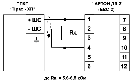
The connection of the linear fire detector “ARTON DL-3” to the control panel “Tiras-XP” must be carried out with a terminating resistor Rk=5.6-6.8 kΩ to match the levels of the next mode of operation. The resistor should beconnected to the BVS-3 unit. The connection is made according to the scheme presented here.
PE “Arton” manufactures and certifies fire smoke and heat detectors in Ukraine for compliance with the requirements of DSTU EN-54: 7-2004 “Fire alarm systems. Point, scattered light, transmitted light or ionization fire detectors” and DSTU EN5 2003 g. “Fire signaling systems. Fire point thermal detectors”.
The requirements of the above standards do not include such a parameter as the area protected by the detector. Therefore, such a parameter is not included in the technical documentation of the detectors produced by our company.
In the technical documentation for detectors produced by our company, the values of the parameters that are measured, which are confirmed by the test protocols when conducting qualification, periodic, standard and certification tests, are given.
The area protected by the detector is rather an indicator of the designer of the fire alarm system than the manufacturer of the component, since this value can be considered only as an average, which significantly depends on the architecture of the object. This parameter can and should be unique for the type of certified detector: point or linear, smoke or thermal, but in no way dependent on the location or form of ownership of the manufacturer.
Requirements for the location of fire detectors on objects and the area protected by the detector are partially reflected in tables 6.1 and 6.2 of the document “State construction standards. Construction equipment and construction. Systems of fire protection measures. DBN В 2.5-56: 2С16.” -Н CEN / TS 54-14: 2009 “Fire alarm and notification systems. Guidelines for planning, design, installation, commissioning, operation and maintenance”.
Secondly, if a detector will be used in the project, which is not in the above-mentioned documents, for example multi-criteria ones, then information about the estimated area protected by the detector may be requested from the manufacturer of such a product.
In the technical documentation for such a product, it is possible and necessary to enter these and other parameters that go beyond the requirements of the above-mentioned regulatory documents, but meet, for example, the requirements of the technical conditions for detectors. However, the inclusion of such a parameter in the technical documentation requires confirmation of its value by appropriate tests and measurements. To do this, it is necessary to carry out a number of procedures, such as the development of the measurement methodology, its coordination in the certification center, conducting measurements there, obtaining a confirming measurement of the test protocol, etc. Naturally, this will also lead to certain financial costs, which cannot but affect the price of the product.
Indeed, some manufacturers of fire detectors in their technical documentation indicate such a parameter as the area protected by one point detector, but even on their websites they provide certificates of conformity of the detectors, which indicate that the detector meets the requirements of ONLY or DSTU EN-54: , or DSTU EN54-5: 2003 and more. Therefore, the question arises, on the basis of the requirements of which document(s) the measurement was carried out, is protected by the area detector, and were such measurements carried out at all? Can such a manufacturer publish the protocol of the certification test of the above-mentioned parameter? In similar cases, it is probably impossible to exclude the fact that the indication of this parameter in the documentation is trivially an advertising move by the manufacturer.
The linear smoke detector Arton-DL is connected to the reception and control devices of the fire department, security and fire department, to devices with sign-changing loops only with the help of the MUSH-DLM loop matching module according to the connection diagrams.
Note. The Arton-DL smoke linear detector is connected to the devices of the “Arton” and “Vector” fire receiving and control series manufactured by PP “Arton” without the use of the MUSH-DLM loop matching module.
Linear smoke detector ARTON-DL1 is connected to the devices of reception and control fire brigades, security and fire brigades, to devices with sign-changing loops only with the help of the MUS-DLM loop matching module according to the given connection schemes. The connection scheme to the Tiras series FACP is indicated here.
Note. The Arton-DL1 linear smoke detector is connected to the devices of the “Arton” and “Vector” fire receiving and control series manufactured by PP “Arton” without using the MUSH-DLM loop matching module.
Connection diagram: View