

ARTON-02P
Product description 
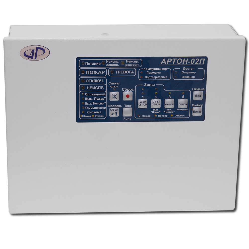
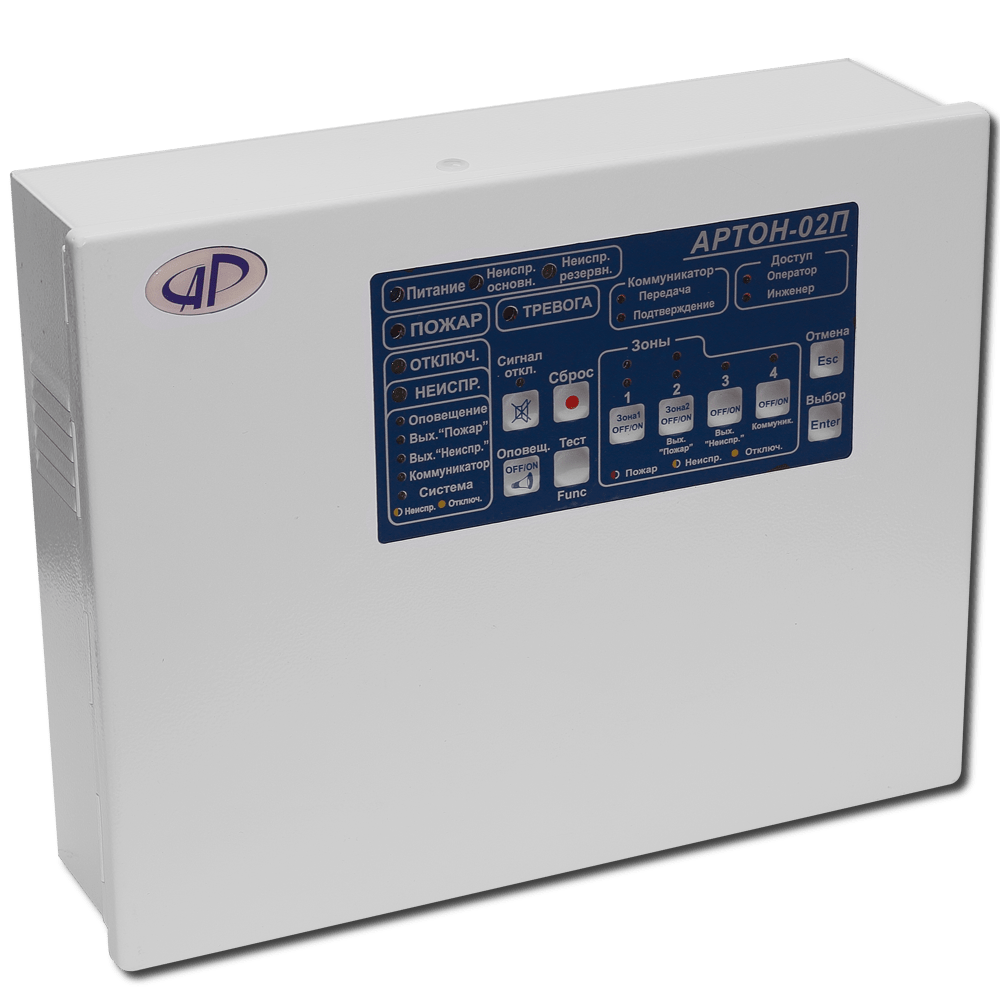
Intended for the organization of centralized and autonomous fire protection of various objects through round-the-clock monitoring of the status of up to 2 alarm loops (AL).
The device meets the requirements of the standards DSTU EN-54-2: 2003/Amendment No. 1 and DSTU EN 54-4:2003 / Amendment No. 2, DSTU-H CEN / TS 54-14:2009.
- Each of the AL can be configured by the consumer as a fire AL without verification, with verification, or with the activation of 2 detectors, and dependencies of types A, B, C can also be set (according to the requirements of DSTU EN-54-2: 2003/ change No. 1);
- The devices determine and display the following statuses of the AL: "On-duty mode", "Attention" (operation of the first detector in the AL), "Fire", "Fault - short circuit", "Fault - open circuit", "Security system disconnected", "malfunction of one of intelligent detectors in the SHS":
- The possibility of connecting passive and active detectors into one control panel, building combined control panels using 2-wire and 4-wire connection schemes;
- Determination of the following types of malfunctions and states: short circuit of the output keys, interruption of the loads of each of the output keys, lack of voltages supplying the output keys and AL, lack of 220V power supply voltage, absence, critical discharge or malfunction of the battery, etc.;
- Availability of outputs: "Fire", "Fault", "Notification" ("Snd1" and "Snd2"), 2 programmable current outputs "AUX1" and "AUX2" and 2 programmable relays "Relay1" and "Relay2" ;
- The possibility of connecting up to 4 independent detectors with chain integrity control (in accordance with the requirements of DSTU-H CEN / TS 54-14:2009);
- The presence of an input for connecting an external backup power source with control of its serviceability;
- There is no need for a current-limiting resistor when connecting detectors of the SPD-3, SPD-3.10, TPT, FT type to the two-wire AL;
- The presence of a separate muting (disabling) alarm button;
- Auto-memory function of the current of the satandby mode of the AL;
- The possibility of changing the detection thresholds of detectors from 1 to 16 mA;
- The possibility of configuring devices using a PC.
Specifications
Characteristic
Value
Overall dimensions:
not more than 200 x 300 x 80 mm
Mass:
no more then 2,5 kg
The device is powered by an alternating current network with a voltage of 187 - 242 V, a frequency of (50 ± 1) Hz and / or a battery (AB) with a voltage of 12 V ± 15% and a nominal capacity of 7 A / h;
The maximum power consumption of the device from the network:
30 W
Maximum current consumption from the battery:
1,0 A
Power consumption from the alternating current network in the alternate mode of operation:
no more then 15 W
The operating time of the device from a fully charged battery in the absence of a network is at least 24 hours in the regular mode of operation, including at least 3 hours in the "FIRE" mode
The maximum number of AL connected to the device:
2
Power supply voltage at open contacts of AL:
15 (± 1 ) V
Output key voltage at rated load:
12 (± 2,0 ) V
The total resistance of the lines (wires) of the SS without taking into account the resistance of the terminating resistor:
no more than 220 ohms
Leakage resistance between the lines of SHS (when the terminating resistor is disconnected), as well as between each line of AL and the device case:
not less than 50 kΩ
The DC current, which is considered by the device as an interruption:
from 0 to 3 mA
The DC current, which is considered by the device as a short-circuit:
not less than 20 mA
Limiting current in the event of a short-circuit in the AL:
no less then 24 mA
The device reacts to a change in the state of the SHS when the duration of this change is at least 80 ms and does not issue a message about the change when the duration is less than 50 ms.;
The device allows you to connect up to 32 active detectors (type SPD-3, SPD-3.5, SPD-3.10, SPT-2B, SPT-ZB, etc.) to each fire alarm system, while the maximum current consumption by all fire detectors in the regular mode of operation should not exceed 3 mA;
The duration of the automatic reset (disconnect time) of the system during the verification of the system;
at least 5 seconds
Duration of waiting for re-activation after resetting of the SHS, upon detection of which the device switches to the "Fire" mode:
( 60 ± 1 ) sec
The device provides connection of a light and sound alarm with a nominal voltage of 12 (± 1.8) V and a consumption current of up to 500 mA
The maximum load current of the power output of 4-wire fire detectors:
200 mA
The maximum load current of the outputs "Fire", "Alarm", "Fault":
40 mA
Average working time before device failure:
no less then 30000 hours
Range of ratings of end resistors:
from 1 kΩ to 3.9 kΩ
The range of ratings of additional current-limiting resistors of active detectors:
from 0 to 1.2 kΩ
Stabilized power supply:
15 (± 0,5 ) V
AL short circuit current:
no less then 60 mA
The maximum current of outputs "Snd1", "Snd2":
500 mA
Maximum current of outputs "AUX1", "AUX2":
300 mA
Useful materials
| Name | Country | Comment | Open | Download |
|---|---|---|---|---|
| Manual | russian | |||
| Сertificate | UA(Ukraine) | Valid from January 14, 2022 to January 13, 2025 | ||
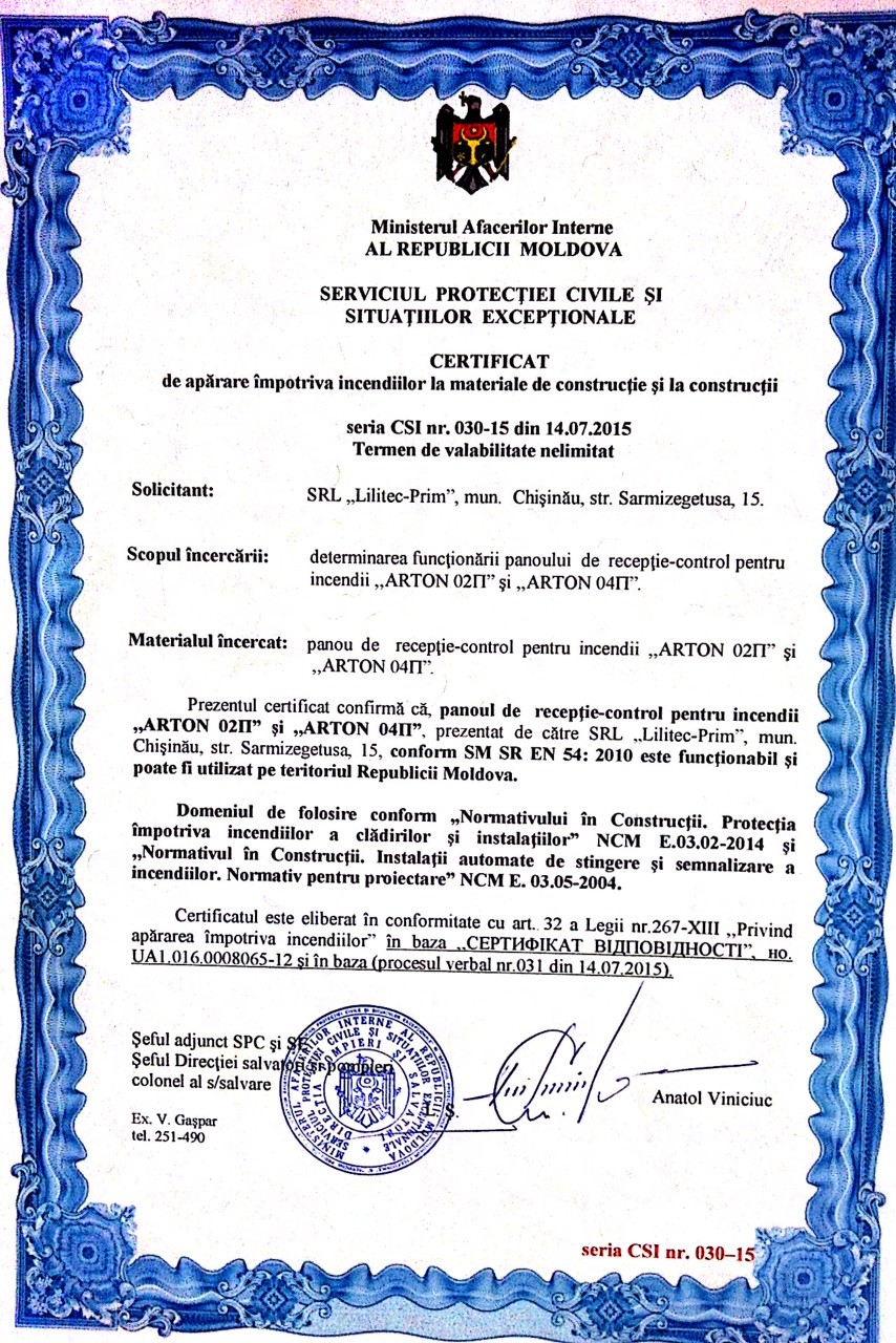
| Сertificate | MD(Moldova) | Expired | ||
| Scheme | Connection diagram of detectors FTL-A1R, FTL-A2R, FTL-BR to FACP "Arton-02P, (-04P), (- 08P)" (in Russian). | |||
| Instruction | Brief instructions for putting into operation PPKP "Arton-08P" ("Arton-02P", "Arton-04P") (in Russian). | |||
| Archive | Manual, photo |
Devices with which it is used
Educational materials
Click to view komponenty_spz_r82.pdf
Click to view komponenty_spz_r83.pdf
Click to view komponenty_spz_r84.pdf
Click to view komponenty_spz_r85.pdf