

ARTON-32P – discontinued
Product description 
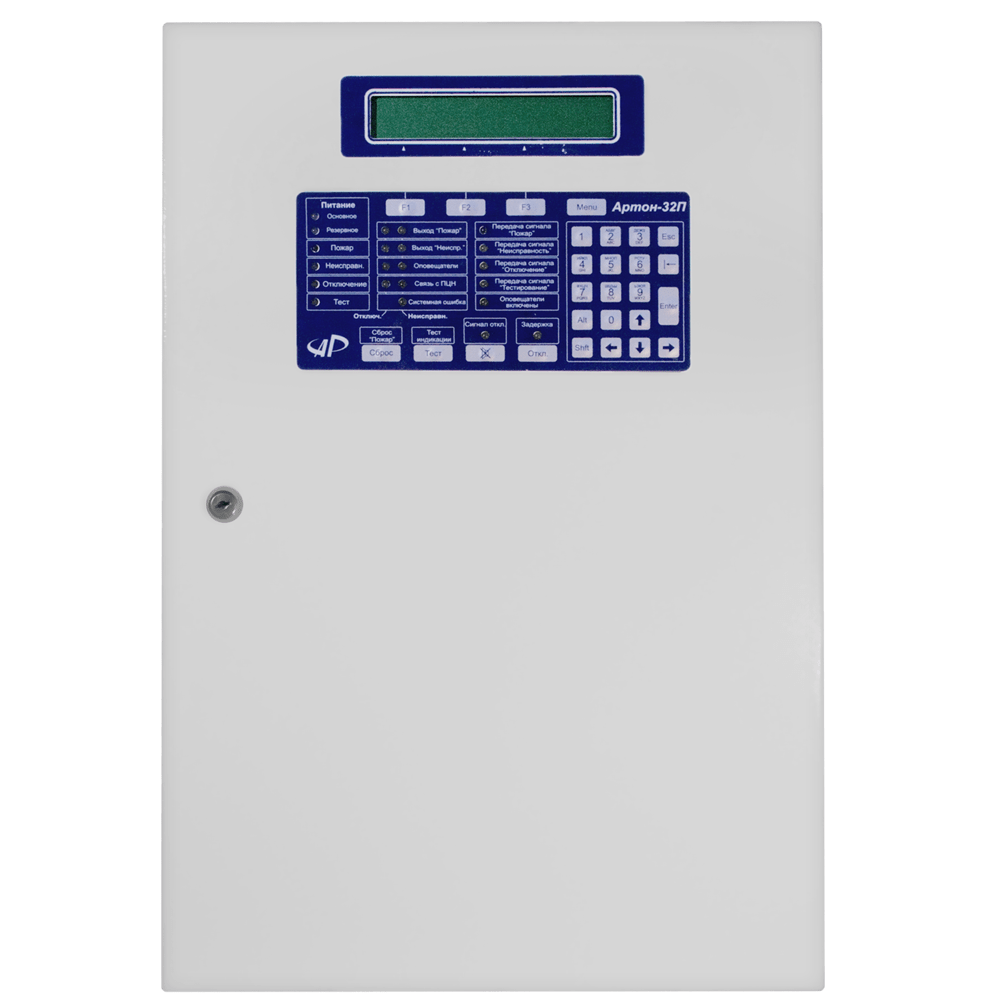
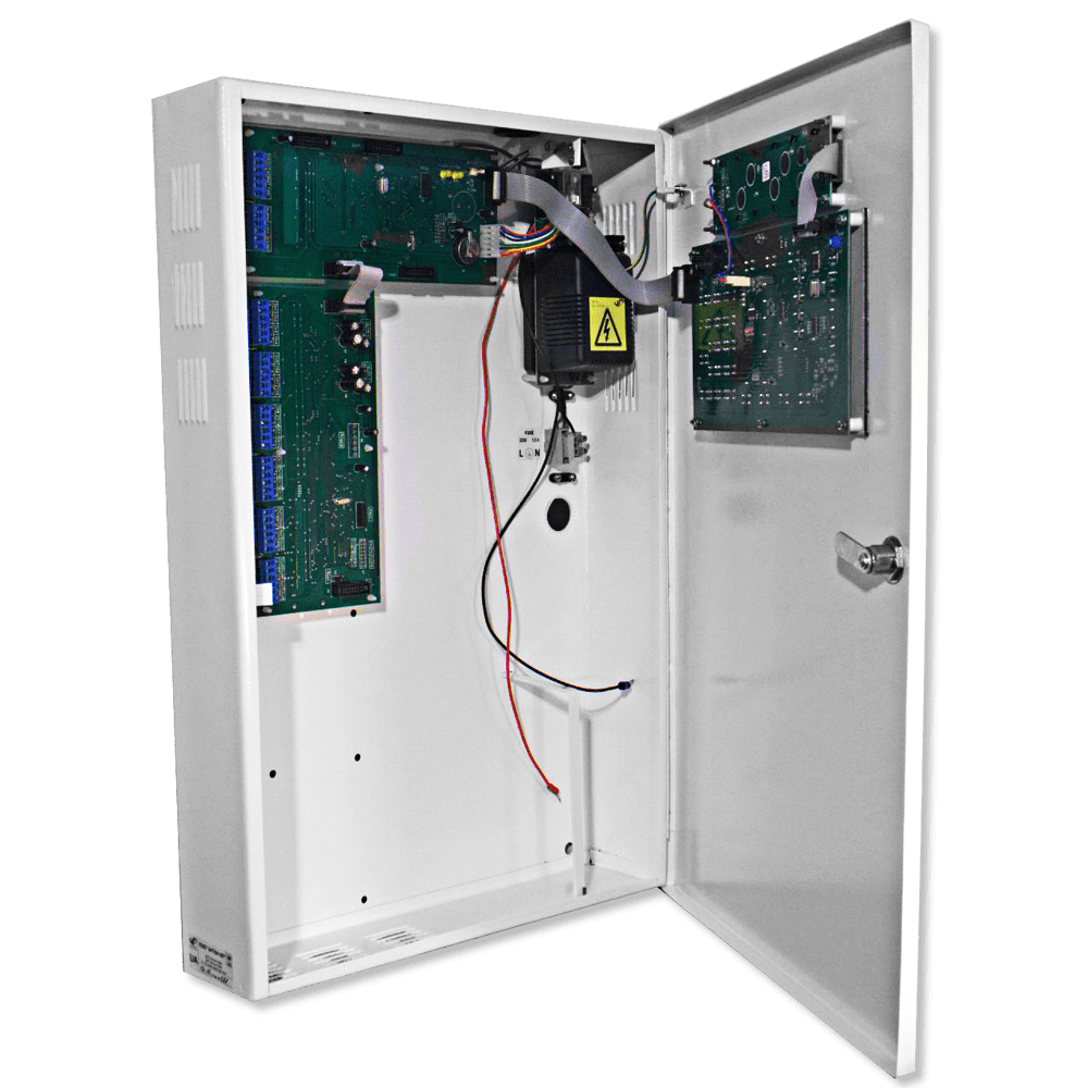
FACP “ARTON-32P” is intended for the organization of centralized and autonomous protection of various objects from fires, through round-the-clock monitoring of the state of up to 32 fire alarm loops, recording of fire or malfunction signals, issuance of alarm notifications (about fire, accidents, malfunctions of unauthorized dissection) on warning devices (light and sound) and on the centralized monitoring panel. The device generates control signals for up to 22 output lines (including the inclusion of control devices for fire extinguishing, smoke removal, facility ventilation systems).
FACP “ARTON-32P” complies with all standards of DSTU EN54 – 2: 2003 and DBN V 2.5-13-98.
- The device determines and displays with optical indicators and on the alphanumeric display:
- general states: modes "Fire", "Fault", "Disconnect", "Test";
- notification of malfunctions: disconnection or malfunction of outputs (fire, malfunction, alert, communication channels with the CNP), system error, key activation delay;
- states of the alarm loops ("Standby mode", "Attention", "Fire", "Short-circuit", "Open circuit", "AL disabled", "AL testing");
- states of output switches ("Short circuit in load", "Load break", "On delay", "Activation", "Disconnect", "Testing");
- state of the power supply unit and battery ("Absence of battery", "Charge of battery", "Critical discharge of battery", "battery normal", "Availability of 220V" or "Absence of 220V", "Charger malfunction");
- The device provides:
- protection against unauthorized access to the inside of the case (opening or breaking the cover);
- automatic recharging of the battery and protection against its incorrect connection;
- protection of all output keys against short-circuits with automatic restoration of the initial state after elimination of the short-circuit;
- control of the integrity of the load chain of all output keys;
- The device implements multi-level access to control functions and the possibility of programming using the built-in keyboard of the following parameters and functions:
- Viewing and setting parameters of AL;
- fixation of the base currents of the AL; (current of AL in standby mode);
- installation of symbolic names of AL;
- viewing and setting parameters of output keys;
- setting symbolic names of output keys;
- changing user and engineer passwords;
- setting user rights to control the AL;
- setting user rights to manage exits;
- event log management.
Specifications
Characteristic
Value
Overall dimensions:
no more than 410 х 610 х 120 mm
Mass:
no more tahan 10 кг
Powering the device;
voltage 220 (+22-33) V frequency (50 ± 1) Hz
The device is powered by sealed, maintenance-free lead-acid batteries with a nominal voltage of 12V, a full charge voltage of 14.4V, a nominal capacity of 16 to 18 Ah, and a final long-term discharge voltage of 10.5V. (batteries is not included in the delivery set) .
The maximum power consumption of the device from the alternating current network, W:
no more than 40
Power consumption from the alternating current network in standby mode, W:
no more than 12
Maximum current consumption from batteries , A:
no more than 2
The maximum current consumption from the batteries in standby mode, A:
no more than 0.55
The maximum current consumption from the battery, when the alternating current network is disconnected and the voltage on the battery is less than (10.5 - 1) V, mA:
no more than 200
Total load of output keys, A:
no more than 0,8
Voltage at the contacts of the open output keys (at the maximum total load of the output keys), V:
8,8 ... 15
Doubled amplitude of pulsations on open output keys, V:
no more than 0,5
Supply voltage at the contacts of the SHS when there is no load: in the 12V AL mode, V:
- 15 ± 0,5
Supply voltage at the contacts of the SHS when there is no load: in the 24V AL mode, V:
- 24 ± 0,5
The total resistance of the signal lines (wires) of the SHS without taking into account the resistance of the terminating resistor, Ohm:
no more than 470
Leakage resistance between the lines of AL, as well as between each line of AL and the device body, kΩ:
no less than 50
Modes of operation of the alarm system according to the type of connected detectors (type of alarm system):
active SHS, passive AL, combined AL
Modes of operation of the Fire Service by type of decision-making about the state of "Fire":
transition to the "Fire" state upon activation of 1 or more FA with or without verification
The value of the increment (increase) of the current of the 1st active detector, relative to the basic current of the SMAL, is programmed by the user and is selected from the range, mA:
0.5 ... 8 in steps of 0.5
The value of the reduction of the current of the first active detector, in relation to the base current of the SMAL, is programmed by the user and is selected from the range, mA:
0.5 ... 8 in steps of 0.5
AL current, which is considered by the device as an interruption, mA:
less than 3
AL current, which is considered by the device as short circuit, mA:
more than 24
The time of automatic reset of the AL in the "Verification" state is set by the user in the interval, seconds:
1 ... 20 in steps of 1
The waiting time for readiness after reset in the "Verification" state is set by the user in the interval, seconds:
1 ... 20 in steps of 1
The waiting time for reactivation after reset in the verification mode is set by the user in the interval , seconds:
1 ... 255 in steps of 1
The device is guaranteed to change its state when the duration of exposure is more than 100ms and does not change its state when the duration of exposure is less than 50ms:
The device allows you to connect up to 32 active detectors (such as SPD-3, SPD-3.5, SPD-3.10, SPT-2B, SPT-3, etc.) to each fire detector, while the maximum current consumption by all active fire detectors located in this fire detector is should not exceed 3 mA:
The output activation delay time is set by the user from the interval , seconds:
0 ... 255 in steps of 1
The time of the active state of the outputs is set by the user from the interval , seconds:
1 ... 65535 in steps of 1
The time of the active period in the passive output state is set by the user from the interval, seconds:
0 ... 25,5 in steps of 0,1
The time of the passive period in the passive output state is set by the user from the interval , seconds:
0 ... 25,5 in steps of 0,1
as of the active period in the active output state is set by the user from the interval , sec:
0 ... 25,5 in steps of 0,1
The time of the passive period in the active output state is set by the user from the interval, seconds:
0 ... 25,5 in steps of 0,1
The duration of transient processes when switching the output from the active to the passive state is set by the user from the interval, seconds:
0 ... 255 in steps of 0,1
Each output has the possibility of setting the inverse mode of operation.
The maximum load current for each of the outputs, mA:
no more than 300
Number of users:
9 (8 operators and 1 engineer)
User password length, characters:
0 ... 16
Time of technical readiness of the device after turning on the power source, seconds:
no more than 30
Average operating time for device failure, h:
no less than 40000
Useful materials
| Name | Country | Comment | Open | Download |
|---|---|---|---|---|
| Manual | russian | |||
| Сertificate | UA(Ukraine) | expired | ||
| Instruction | Основні прийоми роботи при налаштуванні та конфігуруванні різних об'єктів приладів приймально-контрольних пожежників «Артон-16П», «Артон-32П» |

Devices with which it is used
Educational materials
Click to view komponenty_spz_r82.pdf