

SPD-3

Product description 
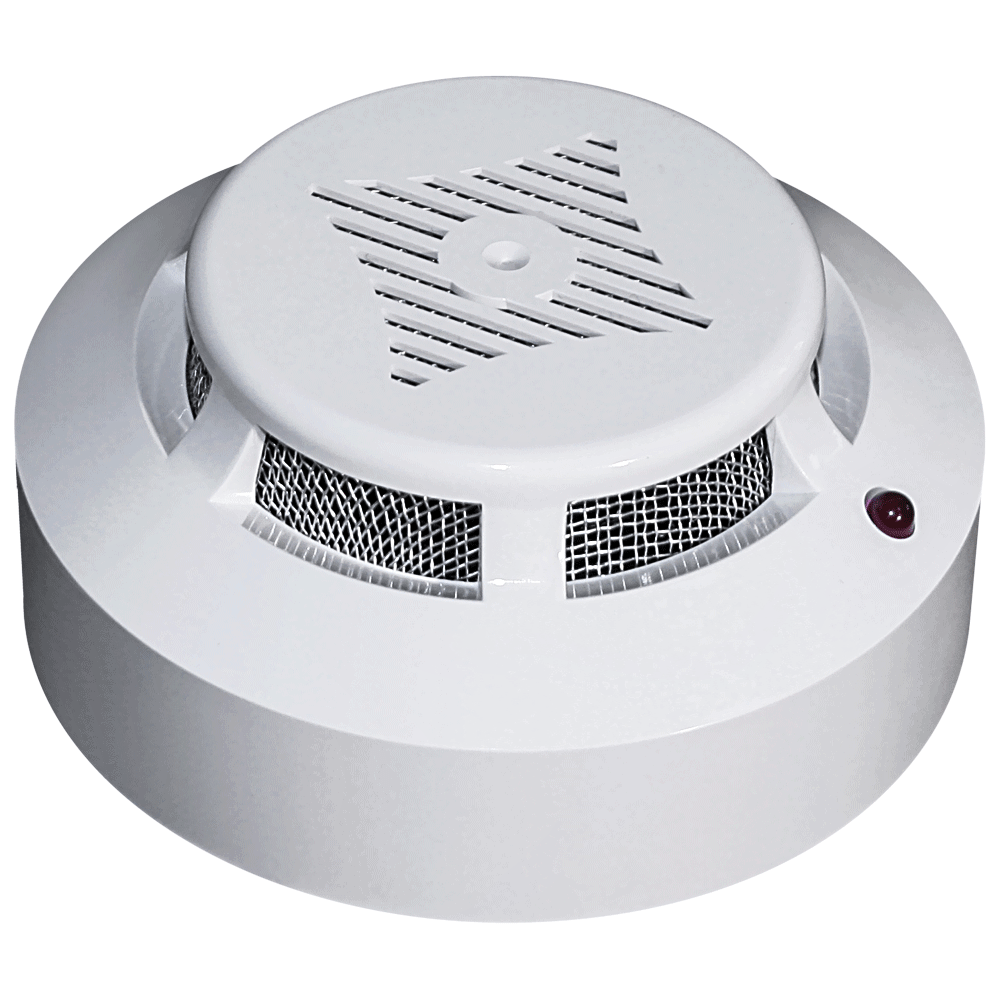
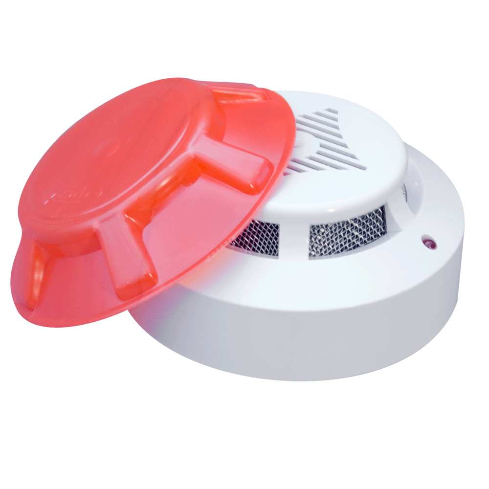
Fire smoke optical point detector is designed to detect fires in closed rooms of various buildings and structures, which are accompanied by the appearance of smoke and the transmission of the “FIRE” signal to the control panel.
- Features:
- 2-wire connection to the control panel
- Indication of the next working mode and the "Fire" mode
- High resistance to false alarm
- Wide range of supply voltage
- Compatibility with various FACP
- The possibility of installation both on the ceiling and on the wall
- Availability of decorative rings for installation on suspended ceilings
- The possibility of connecting off Remote Output
Specifications
Characteristic
Value
Supply voltage range:
10 - 30 V
Current consumption in standby mode:
0.095 mA
The method of connecting to the FACP:
two-wire AL
Overall dimensions:
no more than 100x48 mm
Mass:
no more than 0.15 kg
The presence of an indication of the duty mode:
Yes
Maximum permissible current in FIRE mode:
30 mA
Power off time to return to normal operation mode:
3 sec
The method of forming the output signal:
contactless
Useful materials
| Name | Country | Comment | Open | Download |
|---|---|---|---|---|
| Manual | ukrainian | |||
| Сertificate | UA(Ukraine) | valid from January 14, 2022 to January 13, 2025 | ||
| Сertificate | MD(Moldova) | expired | ||
| Video | Kadet SPD-3 |
|
||
| Scheme | Connection diagram SPD-3 to FACP |

Devices with which it is used
Questions and answers
For normal operation of the SPD-3 detector in the “Fire” mode, the current-limiting resistor must set the current from 8 to 30 mA, with a voltage drop on the detector of at least 8 V. Therefore, for constant current loop with a voltage of 24 V, the value of the resistance of the current-limiting resistor can be within the range of 560 Ohm to 2 kOhm, recommended value 1.5 kOhm. For a constant current loop with a voltage of 12 V, the resistance value of the current limiting resistor can be in the range from 150 Ohms to 510 Ohms. The recommended value is 390 ohms. When connecting SPD-3 to of variable-sign loops, the current-limiting resistor may not be installed, as the current limit in the loop in the “Fire” mode is carried out by the receiving and control device.
It is not possible to connect a VUOS to the SPD-3.2 detector, as this detector does not have a separate output for this, and it is not possible to connect the VUOS in series with the detector in the power supply circuit, as this is prohibited by the DSTU EN 54-7: 2004 standard.
You can solve this problem on our equipment in two ways:
1) Using SPD-3.10 detectors with B4 or B5 bases. See details in the passport for this detector.
2) Using SPD-3 detectors from VUOS, and the loop must be coordinated with the four-wire PPKP through MUSh-2 or MUSh-3 loop matching modules.
Connecting SPD-3 should be done according to the SCHEME. The Rok resistor must be installed at the end of the loop, and not on the control unit itself. The introduction of capacitor C, connected in parallel with Rok, allows you to reduce the switching speed of the variable-sign loop. In addition, it is advisable to ensure the grounding of the common wire of the “GAMMA-132” PPCP electronic unit, for which the lower output of the “Open collector fault” terminal located on the left side of the unit should be connected through a resistor with a resistance of 1 kΩ to the PPCP grounding terminal located on the back wall of the case with right side The control panel itself must be connected to the ground circuit with a resistance of no more than 4 ohms.
Educational materials
Click to view komponenty_spz_r6.5.pdf
Click to view komponenty_spz_67.pdf
Publications
| Edition/Site | № | Year | Title of the article | Open | Download | SECURITY.UA | 3 | 2014 | Connection diagrams of smoke fire detectors. (Part 2) | SECURITY.UA | 3 | 2014 | Connection diagrams of smoke fire detectors. (Part 3) | SECURITY.UA | 3 | 2014 | Connection diagrams of smoke fire detectors. (Part 4) | SECURITY.UA | 3 | 2014 | Connection diagrams of smoke fire detectors. (Part 5) | www.sec.ru | 1 | 2014 | Wiring diagrams for smoke detectors (Part 2) | www.sec.ru | 1 | 2014 | Wiring diagrams for smoke detectors (Part 3) | www.sec.ru | 1 | 2014 | Wiring diagrams for smoke detectors (Part 4) | www.sec.ru | 1 | 2014 | Wiring diagrams for smoke detectors (Part 5) |
|---|---|---|---|---|---|
| www.sec.ru | 3 | 2014 | Smoke optical-electronic point fire detectors. Basic circuit solutions. Part 1.1. Flowcharts | www.sec.ru | 3 | 2014 | Smoke optical-electronic point fire detectors. Basic circuit solutions. Part 1.2. Flowcharts | www.sec.ru | 3 | 2014 | Smoke optical-electronic point fire detectors. Basic circuit solutions. Part 1.3. Flowcharts | www.sec.ru | 3 | 2014 | Smoke optical-electronic point fire detectors. Basic circuit solutions. Part 1.4. Flowcharts | www.sec.ru | 3 | 2014 | Smoke optical-electronic point fire detectors. Basic circuit solutions. Part 1.5. Flowcharts | www.sec.ru | 3 | 2014 | Smoke optical-electronic point fire detectors. Basic circuit solutions. Part 2.1. Transistor photo amplifiers | www.sec.ru | 3 | 2014 | Smoke optical-electronic point fire detectors. Basic circuit solutions. Part 2.2. Transistor photo amplifiers | www.sec.ru | 3 | 2014 | Smoke optical-electronic point fire detectors. Basic circuit solutions. Part 2.3. Transistor photo amplifiers | www.sec.ru | 3 | 2014 | Smoke optical-electronic point fire detectors. Basic circuit solutions. Part 3. IR Emitters | www.sec.ru | 3 | 2014 | Smoke optical-electronic point fire detectors. Basic circuit solutions. Part 4.1 Fire detector output stage | www.sec.ru | 3 | 2014 | Smoke optical-electronic point fire detectors. Basic circuit solutions. Part 4.2 Fire detector output stage |